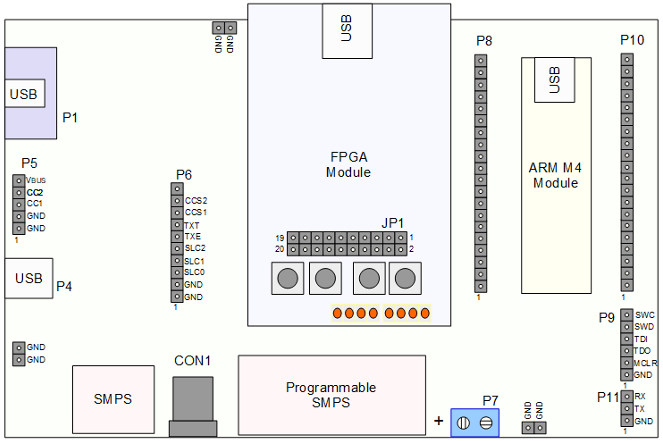
The major components of the board are shown below. On the left side are the main USB data connections. In the middle is an Opal Kelly XEM7001 FPGA module, and on the right hand side is a standard 40 pin DIP module that usually is loaded with a Mikroe (a.k.a MikroElektronika) MPU module with an ARM M4, known as the MINI-M4. However, Mikroe have compatible modules with several other MPU types, which may be inserted into the same socket.

Opal Kelly XEM7001 FPGA daughter module which contains PD protocol logic, and memory for the PD protocol and policy stack. The ARM M4 MPU module is used for system policy C code etc.
Features
Specific features of the board are:
- General Purpose USB Power Delivery Firmware development board.
- Operates as stand alone USB Type-C PD source, sink or dual role.
- Roles and requested power levels may be set by jumpers in stand alone mode.
- 4 internal power regulators support multiple power scenarios. Max 3A 28V output power.
- Separate FPGA and ARM modules give good access for RTL and C code development and testing.
- PD specific, real time debug is available through the USB port on the MINI-M4 module. This may be connected to a Windows PC for additional PD state monitoring and control. A vital debug resource during customization. A Windows PC monitor program is provided.
- Type-C baseband and full speed USB communications through the board to simulate real user scenarios.
- Board runs OT91xx RTL directly for evaluation purposes.
- Can be used for IP compliance testing.
Board Ports
The board is pinned for easy debug access as follows: